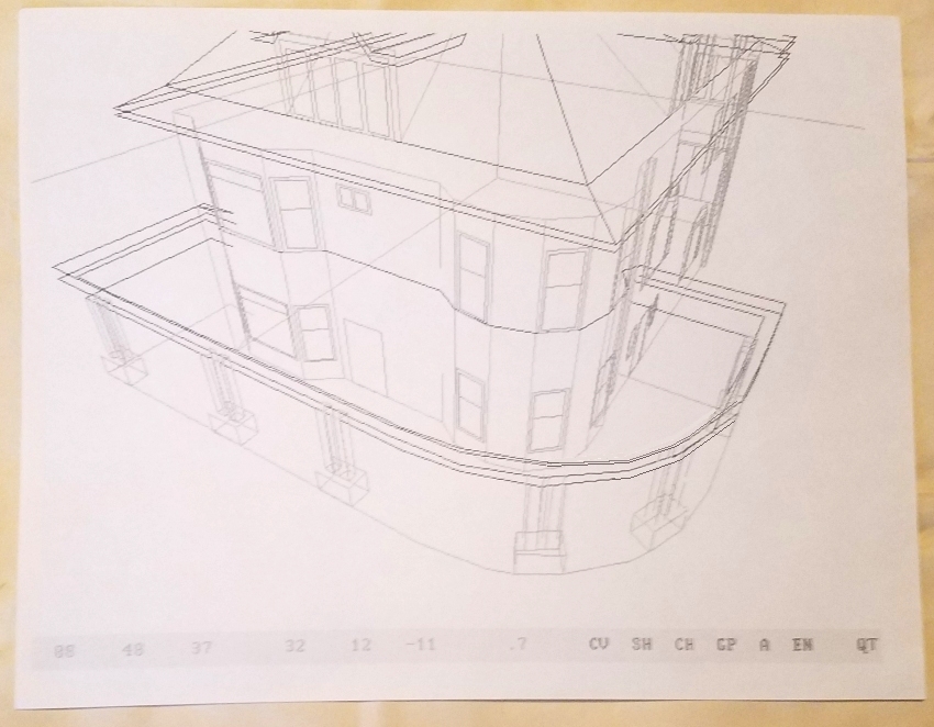
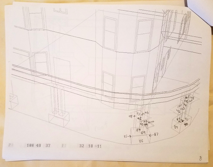
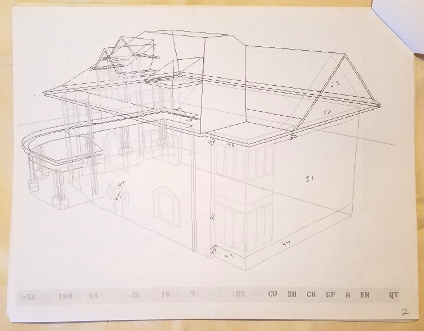
RogCAD home <--- back to RogCAD home page A simple tool .. becomes a hobby .. becomes a great tool 1. Why I developed RogCAD 2. Details about RogCAD's design methods 3. RogCAD's inception and history RogCAD is freeware ================================== PART ONE Why I developed RogCAD ================================== The high-end 3D CAD software packages I trialed long ago were complicated, large software packages that had a large draw on my computer's CPU and RAM resources. I found them vexing for 3D modeling; certainly when compared to the text-file data-entry RogCAD system. With the exception of the free and open-source Blender, I found their fully functional versions to be expensive and that they: required installation, registration and licensing, and required Internet interfacing at various levels. I can't trial every CAD package out there. I eventually gave up on them because I wanted something simpler. Many of the problems I had with complex CAD software stem from the fact that they are primarily mouse-driven. ---- RogCAD is keyboard data-entry 3D CAD software. For years, I continued to upgrade RogCAD as a result of purchasing -- for the sake of comparison -- several inexpensive 3D CAD software packages. They turned out to be merely toys; there was no possibility of doing real design work with them. That was many years ago, in the days of purchasing software in a box at your local Best Buy. As for high-end CAD software packages, I consider them to be a good fit for professional engineers, designers, architects and animators who can get a return on their schooling and purchase investment by virtue of the fees they charge their clients. Also a good fit for geniuses. RogCAD cannot compare with most of the high-end software if photo-realism is routinely required. But any design that can be modeled using the most sophisticated software can be modeled in RogCAD: One does not need to attain photo-realism in order to obtain a very effective level of realism; and any facade material can be imported into RogCAD and incorporated in a perspectively correct manner. Sunlight shadowing can also be added at the final stage of modeling. The tutorial/reference document is lengthy; but one to three days of reading, watching the demonstration videos and doing your own experimentation will turn you into capable RogCAD modeler. Every time I've returned to RogCAD after experimenting with complicated 3D CAD software, I've been deeply struck by the difference in the experience -- that of complete and calming stability, simplicity, and cooperativeness. The unlimited design flexibility of RogCAD makes it an even better experience. (The fact that I find magic in seeing numbers become images is a further bonus that would be hard to overstate.) Professional 3D CAD modelers who need to do a wide variety of design tasks can spend years becoming fully proficient with their high-end software. When a designer/remodeler associate of mine was unable to model a design for his client using his expensive software, I modeled it in RogCAD for the appreciative client. As mentioned on the RogCAD home page: I developed RogCAD because I wanted a simpler 3D CAD system with complete flexibility of design. Any level of architectural realism beyond what I typically aim for in my RogCAD models can be very time-consuming and expensive, regardless of which software one is using. If a special circumstance arises, I can bump up the level of realism in a RogCAD model to an entirely suitable degree. Therefore, outside of machining applications or 3D printing, I never consider using anything but RogCAD. Simple, accurate, lightweight, flexible, stable, no installation.. and fun. If you like simplicity and are comfortable working with simply numbers, then RogCAD might be for you. System requirements Blender RogCAD ------------------- ------- ------ computer type 64-bit quad- any computer core CPU with old or new SSE2 support disk space multi-GB 600 KB (apx 1/2000 of Blender's) RAM memory minimum 8 GB 9 MB (apx 1/1000 of Blender's) display card 2 GB GPU any display card OpenGL 4.3 Features Blender RogCAD ------------------- ------- ------ modeling resolution unlimited unlimited limitation of design none none import backgrounds? yes yes Import and export objects to and from other CAD software? yes no 3D physical fabrication support? yes no ================================= PART TWO RogCAD's design power ================================= RogCAD is for those who appreciate its "by the numbers" methodology. We typically think of mouse-driven CAD software as giving us quick gratification. But RogCAD's "by the numbers" data-entry can yield quick gratification as well. One need only run the program after entering just a bit of data to get the gratification of seeing something simple modeled on the screen. One is thus provided with motivation to move forward with the design. RogCAD is the essence of straightforwardness when it comes to data-entry and data-editing because it is just numbers, and you are always in control of those numbers which you can see with your own eyes. Minimal data-entry goes a long way. RogCAD's automation methodology and transformations allow you to generate designs quickly. As with the mouse-driven data-entry method used by expensive software, RogCAD requires that the user supply just two points of a proposed cubic element, such as a wall of a given thickness, height and length. The RogCAD software automatically defines the remaining six points, as well as the connecting lines and planes of that cubic element. Therefore, the RogCAD user is actually entering far less data than you might expect in order to achieve a given design. RogCAD's data-entry system provides other automatically generated elements as well by virtue of creating a string of modifiable cubic elements of whatever spacing and number of elements the CAD user specifies. Thus quickly generated are elements such as mitered and beveled framing members, rows of windows, etc. RogCAD's transformation routines are snippets of text which the CAD user can paste into the data text files to modify specified ranges of data points in a variety of ways. That is how elements get rotated, translated (slid), deformed and resized to suit the CAD user's needs. These transformation routines are used in conjunction with libraries of objects as well as in conjunction with blocks of data that one wishes to repeat in a rotated or translated manner. For instance, you can both modify and relocate cabinets, windows, walls, doors, appliances and furniture quickly with the transformation routines. Just a couple of the many transformation snippets: -------------------------------- RESIZE: first, last, multX, multY, multZ 401 598 1 1 1.15 -------------------------------- ------------------------------------------ XROTATETRANSLATE: first, last, xangle, tranx, trany, tranz 1 268 90 112.25 50.82 0 ------------------------------------------ RogCAD has a powerful curved surface routine which allows one to create any type of irregularly curved surface. Boat hulls are easy for RogCAD. And again, it's just numbers which you enter into a text file. It puts the CAD user in complete control of the output. RogCAD can also combine its curve routine with strings of cubic elements: Those cubic elements are thus repeated along any curve the CAD user wishes. My first use of that combined routine was in producing (hexagonal) port-holes on the curving hull of a ship. Spiral staircases are the most obvious application of this feature. ------------------------------------------------------------- ZWRAP: start first, start last, angle per cube, how many, lift value 2001 2008 1.44 26 .223 ------------------------------------------------------------- The features just described in this section are what makes RogCAD about as fast for design as is any expensive software, until one gets into machine design. The RogCAD program code has a "good enough" algorithm for automatic surface modeling with automatic shading for light-source direction. Thoughtful definition of project elements assures accurate plane-sorting for surface modeling. RogCAD's automatic surface modeling generates a smooth gradient lighting differential on curved surfaces. RogCAD also provides a macro text file for doing customized automatic surface modeling, should the CAD user wish to make further enhancements. Building and using a macro text file for automatic surface modeling has nil effect on total project time. The macro text file is always 100 percent accurate because it is built by the CAD user manually. That macro file itself consists of many automatic methods, so it is a powerful tool. It gets built quickly by the CAD user as he proceeds with, and tests, his design. Its one limitation is that it must be tweaked if one significantly changes one's perspective point. ===================== PART THREE History ===================== RogCAD began life as a strictly text-based CAD program in 1993. I was designing a complicated structure which I had proposed to build for a client, and I wanted to present them with a perspective drawing on paper. I soon discovered that there is no non-arbitrary method for setting up perspective lines so as to achieve a realistic camera's eye view. I wished I had 3D CAD software, but the only computer I owned at the time was an IBM 8088 with a monitor that could display only text, so no commercial CAD software would have been of any use even if I could have afforded such software. What to do. It occurred to me to try to write a simple computer program that would output raw data which could then be plotted on paper. At first, it struck me as something that was way beyond me. I knew enough math to appreciate how messy things can get when you try to project a three-dimensional object onto a floating two-dimensional plane, that plane itself being something that you must define mathematically. But the problem kept tugging at me and I sat down the next morning to task myself with it. (Link to original hand-written derivations is at the bottom of this page.) That night I had my first version ready for testing: ------------------------------------------------------- 1 REM DECK1.BAS 10 INPUT XS 12 INPUT YS 14 INPUT ZS 20 PRINT 30 X=(((150-XS)*(345-(2*YS)-ZS))+(XS*(250-ZS-(2*YS))))/ (700-(3*XS)-ZS-(2*YS)) 40 Y=(((100*X)-(YS*X)-(100*XS)+(YS*XS))/(150-XS))+YS 50 Z=(((50*X)-(ZS*X)-(50*XS)+(ZS*XS))/(150-XS))+ZS 60 M=(((X-73.93)^2)+((Y-49.29)^2)+((Z-24.64)^2))^.5 70 PRINT M: REM magnitude 80 PRINT 90 C=(((X-73.93)*(-.583))+((Y-49.29)*(-.392))+ ((Z-24.64)*(2.533)))/(2.63*M) 100 PRINT 110 PRINT "ANGLE = ARCOS "C 120 END ------------------------------------------------------- This first version was capable only of handling one pre-selected perspective point and one pre-selected focal point, and the program had to be run one time for each data point of the proposed structure. I selected 41 data points which represented 41 vertices on the proposed structure. I ran the program and it supplied me with an angle and a magnitude. I plotted the point on a piece of paper and then ran the program another 40 times. It was very exciting to see each plotted point land at its expected spot on the paper. I connected the points with a straight-edge. It was magical as the outline of the structure appeared before my eyes. (I then filled in the remaining architectural details by way of visual extrapolation.) [ QB64 IDE links here ] I took a very over-complicated approach to the problem as a result of following a natural inclination to mimic the real life situation -- I used vectors to define an image plane floating in space, onto which an object would be projected. This is messier than just having a simple image plane defined on the X and Z axis, using a simple trigonometric projection, then rotating the object, which is how it's normally done. But it never occured to me to do it the latter way since the floating image plane directly simulates the real-life situation of a person changing their location (perspective point) in relation to a stationary architectural object. This approach turned out be fortuitous, since it easily allows the user to specify a particular perspective point in three dimensional space, as well as a particular focal point (without me -- the software engineer -- having to work out some set of hideous transformations). And that is well suited to a user who likes or needs to take a technical, accurate or analytical approach. It also worked out well for the future of the software, since it provided an easy way to upgrade it while keeping track of shifting perspectives and focal points. These were features I added after I got my AT-286 computer with an EGA graphics monitor in 1995. The on-screen graphics provided by the 286 gave me an environment where I could expand the software's features endlessly. The program-code grew from twelve lines to ten thousand lines, which is still tiny by 3D CAD standards. ---- My first upgrade was to allow for user-specified perspective and focal points at run-time, along with the capacity to go inside a structure, which greatly complicated the already complicated calculator kernel which performs the image-projection. Here is that upgraded image-projection program-code. It's less than one percent of RogCAD's current program code, but it's the most magical part. For LN = FL(GB) To LL(GB) 1045 inc = 299 1050 If DT = 1 Then DT = 0: G = SP(LN): GoTo 1090 G = FP(LN): DT = 1 1070: If ((X(G) * L) + (Y(G) * M) + (Z(G) * N)) > ((L * L) + (M * M) + (N * N)) Then GoTo 3070 If DT = 1 Then GoTo 1100 1090: If ((X(G) * L) + (Y(G) * M) + (Z(G) * N)) > ((L * L) + (M * M) + (N * N)) Then GoTo 3120 1100: W = ((A * A) + (B * B) + (C * C) - (A * X(G)) - (B * Y(G)) - (C * Z(G))) [ W is then the denominator in the following three equations. ] R(G) = (((A * I) * (A - X(G))) + (B * B * X(G)) + (C * C * X(G)) - (B * X(G) * Y(G)) - (C * X(G) * Z(G)) + ((B * J) * (A - X(G))) + ((C * K) * (A - X(G))) - ((B * Y(G)) * (A - X(G))) - ((C * Z(G)) * (A - X(G)))) / W S(G) = (((B * J) * (B - Y(G))) + (A * A * Y(G)) + (C * C * Y(G)) - (A * Y(G) * X(G)) - (C * Y(G) * Z(G)) + ((A * I) * (B - Y(G))) + ((C * K) * (B - Y(G))) - ((A * X(G)) * (B - Y(G))) - ((C * Z(G)) * (B - Y(G)))) / W T(G) = (((C * K) * (C - Z(G))) + (A * A * Z(G)) + (B * B * Z(G)) - (A * Z(G) * X(G)) - (B * Z(G) * Y(G)) + ((A * I) * (C - Z(G))) + ((B * J) * (C - Z(G))) - ((A * X(G)) * (C - Z(G))) - ((B * Y(G)) * (C - Z(G)))) / W [ R(G), S(G) and T(G) are then inserted into the following two equations. ] U(G) = (((R(G) - L) ^ 2) + ((S(G) - M) ^ 2) + ((T(G) - N) ^ 2)) ^ 0.5 V(G) = (((R(G) - L) * (R(8001) - L)) + ((S(G) - M) * (S(8001) - M)) + ((T(G) - N) * (T(8001) - N))) / (U(G) * ((((R(8001) - L) ^ 2) + ((S(8001) - M) ^ 2) + ((T(8001) - N) ^ 2)) ^ 0.5)) [ U(G) and V(G) are then inserted into the following equation. ] XX(G) = U(G) * V(G) If V(G) > 0.9999 Or V(G) < -0.9999 Then YY(G) = 0: GoTo 1200 YY(G) = U(G) * ((1 - ((V(G)) ^ 2)) ^ 0.5) If ((L * S(G)) - (M * R(G))) < 0 Then YY(G) = (-1 * YY(G)) 1200: If CHK = 0 Then CHK = 1: GoTo 950 'If AP = 1 Then CHAIN "ENHANCE.MOD" IF DT = 1 THEN X(G) = XR(G) - TX: Y(G) = YR(G) - TY Z(G) = ZR(G) - TZ: GOTO 1050 END IF X(G) = XR(G) - TX: Y(G) = YR(G) - TY: Z(G) = ZR(G) - TZ 1250: GY(FP(LN)) = (MM * 15.2 * YY(FP(LN))) + 680 + HSH GX(FP(LN)) = (MM * (-15.2) * XX(FP(LN))) + 430 - VSH GY(SP(LN)) = (MM * 15.2 * YY(SP(LN))) + 680 + HSH GX(SP(LN)) = (MM * (-15.2) * XX(SP(LN))) + 430 - VSH If ICHK = 1 Then GoTo 1280 'If SS2$ = "Hide" Then READSWITCH = 1 'If SS2$ = "Show" Then READSWITCH = 2: S3 = 1 If READSWITCH = 1 Then GoTo 1290 1280: viewport.Line (GY(FP(LN)), GX(FP(LN)))-(GY(SP(LN)), GX(SP(LN))), RGB(redd(cdex), green(cdex), blue(cdex)) 1290 Next LN 3070 : INC = INC - 1 IF INC = 0 THEN INC = 299: DT = 0: X(G) = XR(G) - TX: Y(G) = YR(G) - TY: Z(G) = ZR(G) - TZ: GX(FP(LN)) = 999: GOTO 1290 X(G) = ((INC / 299) * (TEMX(G) - X(SP(LN)))) + X(SP(LN)) Y(G) = ((INC / 299) * (TEMY(G) - Y(SP(LN)))) + Y(SP(LN)) Z(G) = ((INC / 299) * (TEMZ(G) - Z(SP(LN)))) + Z(SP(LN)) GOTO 1070 3120 : INC = INC - 1 IF INC = 0 THEN INC = 299: DT = 0: X(G) = XR(G) - TX: Y(G) = YR(G) - TY: Z(G) = ZR(G) - TZ: GX(SP(LN)) = 999: GOTO 1290 X(G) = ((INC / 299) * (TEMX(G) - X(FP(LN)))) + X(FP(LN)) Y(G) = ((INC / 299) * (TEMY(G) - Y(FP(LN)))) + Y(FP(LN)) Z(G) = ((INC / 299) * (TEMZ(G) - Z(FP(LN)))) + Z(FP(LN)) GOTO 1090 ===================================== From the early days of RogCAD. Five print-outs from the design-phase of the Hanson project of 1997: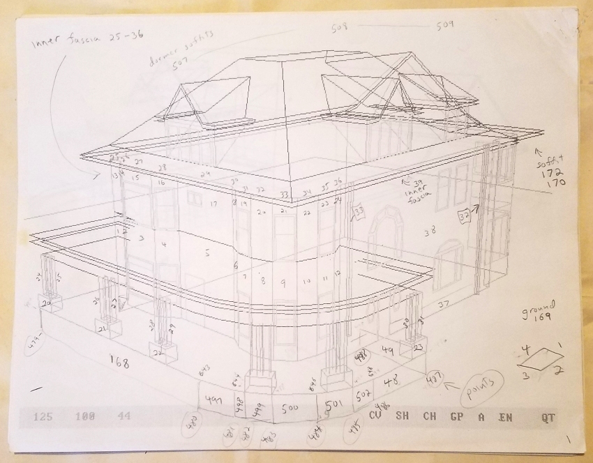
Original hand-written image projection derivations RogCAD home RogCAD complete code Updated 03/27/2024