<-- RogCAD home <-- RogCAD code - complete RogCAD history and hand-written derivations ------------------------------------------- RogCAD began life as a strictly text-output CAD program in 1993. I was designing a complicated structure which I had proposed to build for a client, and I wanted to present them with a perspective drawing on paper. I soon discovered that there is no non-arbitrary method for setting up perspective lines for achieving a realistic camera's eye view. I wished I had 3D CAD software, but the only computer I owned at the time was an IBM 8088 with a monitor that could display only text, so no commercial CAD software would have been of any use even if I could have afforded such software. What to do. It occurred to me to try to write a simple computer program that would output raw data which could then be plotted on paper. At first, it struck me as something that was way beyond me. I knew enough math to appreciate how messy things can get when you try to project a three-dimensional object onto a floating two-dimensional plane, that plane itself being something that you must define mathematically. (My reason for using that particular approach is explained below the hand-written derivation images.) But the problem kept tugging at me and I sat down the next morning to task myself with it. That night I had my first version ready for testing: ------------------------------------------------------- 1 REM DECK1.BAS 10 INPUT XS 12 INPUT YS 14 INPUT ZS 20 PRINT 30 X=(((150-XS)*(345-(2*YS)-ZS))+(XS*(250-ZS-(2*YS))))/ (700-(3*XS)-ZS-(2*YS)) [That value for X is then inserted into equations that define Y and Z] 40 Y=(((100*X)-(YS*X)-(100*XS)+(YS*XS))/(150-XS))+YS 50 Z=(((50*X)-(ZS*X)-(50*XS)+(ZS*XS))/(150-XS))+ZS [Those values for X, Y and Z are then inserted into an equation to define M] 60 M=(((X-73.93)^2)+((Y-49.29)^2)+((Z-24.64)^2))^.5 70 PRINT M: REM magnitude 80 PRINT [Those values for X, Y, Z and M are then inserted into an equation to define C] 90 C=(((X-73.93)*(-.583))+((Y-49.29)*(-.392))+ ((Z-24.64)*(2.533)))/(2.63*M) 100 PRINT 110 PRINT "ANGLE = ARCOS "C 120 END ------------------------------------------------------- That first version was capable only of handling one pre-selected perspective point and one pre-selected focal point, and the program had to be run one time for each data point of the proposed structure. I selected 41 data points which represented 41 vertices on the proposed structure. I ran the program and it supplied me with an angle and a magnitude. I plotted the point on a piece of paper and then ran the program another 40 times. It was very exciting to see each plotted point land at its expected spot on the paper. I connected the points with a straight-edge. It was magical as the outline of the structure appeared before my eyes. (I then filled in the remaining architectural details by way of visual extrapolation.) The rest of the story is beneath these images of derivations: Original notes and derivations for RogCAD, April 1993pre-CAD planning sketch
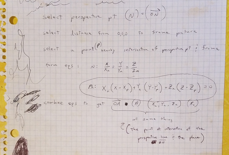
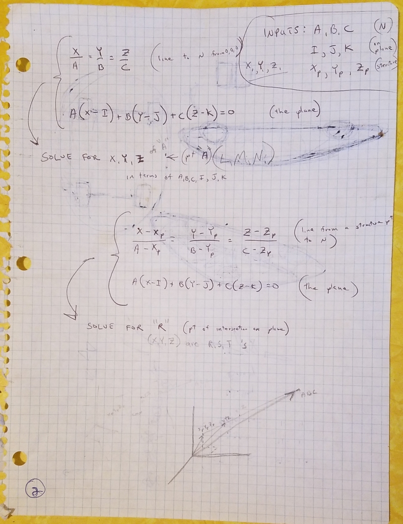
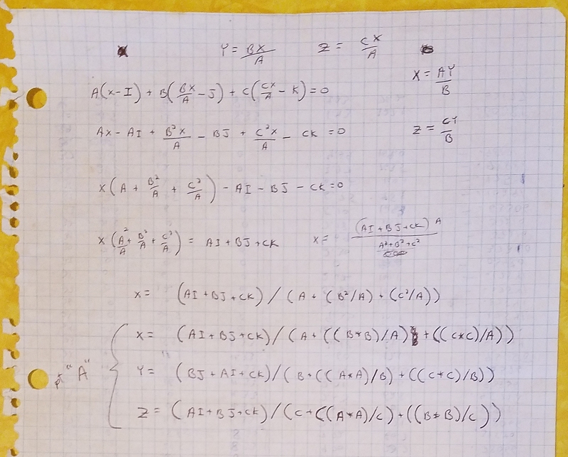
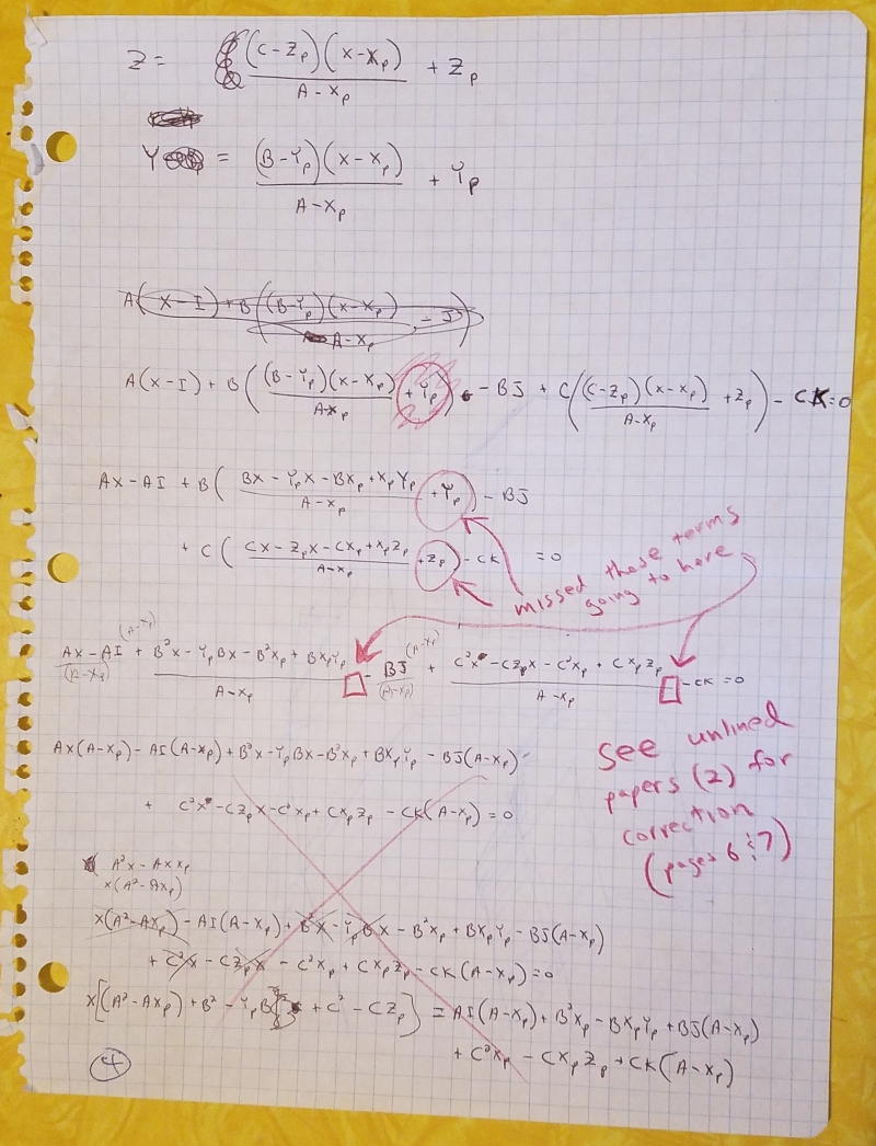
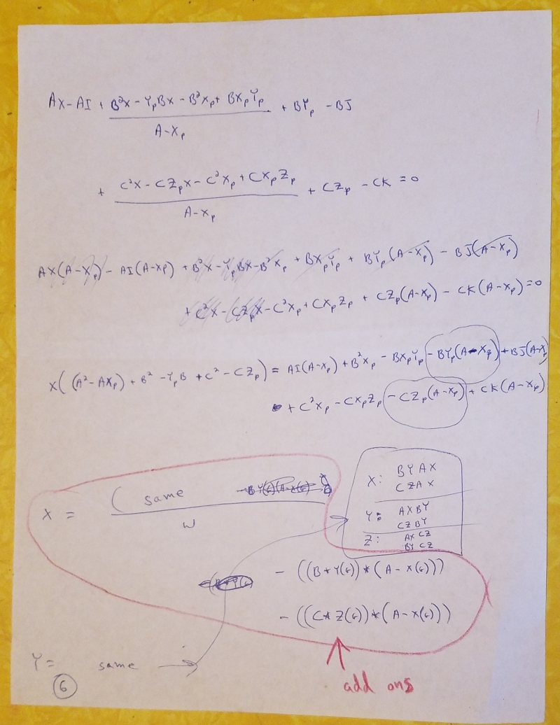
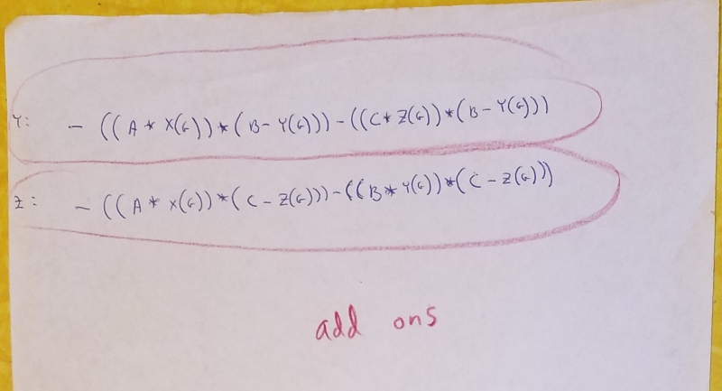
The first nine images below are of the non-generalized derivation (pre-defined perspective point and focal point) of the floating image plane and projection of a structure. The second batch of nine images is of the generalized derivation (variable perspective point and focal point) which is much more complicated. Vector cross-product is used to create a floating image plane with a normal vector that passes through the origin of the xyz axes. Points on the structure are projected onto the floating image plane. Vector dot-product is used to test from which side of the z-axis each projected point stems. After the initial vector considerations, it's just algebra. But the magic of algebra fascinates me, especially when it goes on for many pages and it actually works. First nine images, non-generalized:

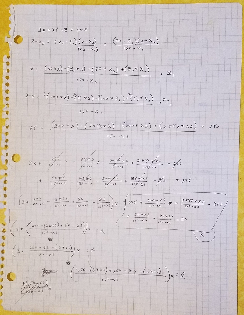
Those derivations produced the original program code for a specific perspective point and focal point:
The program print-out on the dot-matrix printer:
The first RogCAD output. The points had to be plotted on paper, as I had only an IBM XT with a text-only monitor:
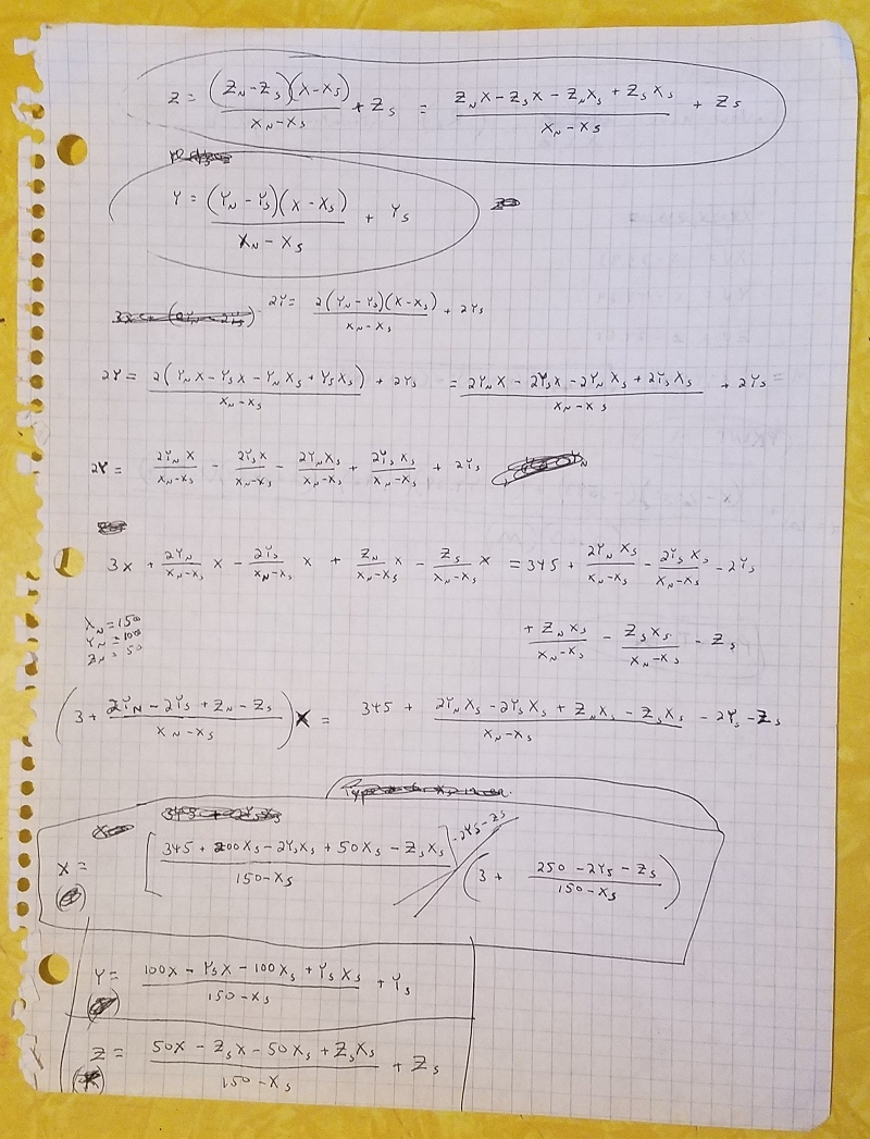
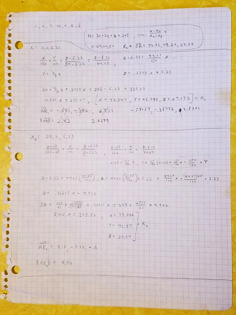
Derivation of floating image plane and projection of structure, generalized, next nine images:

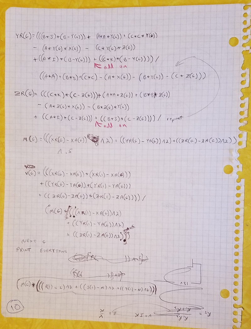
The generalized calculator kernel print-out on the dot-matrix printer:
I took an over-complicated approach to the problem as a result of following a natural inclination to mimic the real life situation -- I used vectors to define an image plane floating in space, onto which an object would be projected. This is messier than just having a simple image plane defined on the X and Z axis, using a simple trigonometric projection, then rotating the object, which is how it's normally done. But it never occured to me to do it the latter way since the floating image plane directly simulates the real-life situation of a person changing their location (perspective point) in relation to a stationary architectural object. This approach turned out be fortuitous, since it easily allows the user to specify a particular perspective point in three dimensional space, as well as a particular focal point (without me -- the software engineer -- having to work out some set of hideous transformations). And that is well suited to a user who likes or needs to take a technical, accurate or analytical approach. It also worked out well for the future of the software, since it provided an easy way to upgrade it while keeping track of shifting perspectives and focal points. These were features I added after I got my AT-286 computer with an EGA graphics monitor in 1995. The on-screen graphics provided by the 286 gave me an environment where I could expand the software's features endlessly. The program-code grew from twelve lines to ten thousand lines, which is still tiny by 3D CAD standards. ---- As seen in the derivations section higher on this page, my first upgrade was to allow for user-specified perspectives and focal points at run-time, which greatly complicated the already complicated calculator kernel which performs the image projection. My second upgrade was to allow the user to take his perspective point inside a structure, which added complexity adjacent to (above and below) the kernel code. Here is that upgraded image-projection program-code (in a tidier format than the dot-matrix print-out above). It's less than one percent of RogCAD's current program code, but it's the most magical part. For LN = FL(GB) To LL(GB) 1045 inc = 299 1050 If DT = 1 Then DT = 0: G = SP(LN): GoTo 1090 G = FP(LN): DT = 1 1070: If ((X(G) * L) + (Y(G) * M) + (Z(G) * N)) > ((L * L) + (M * M) + (N * N)) Then GoTo 3070 If DT = 1 Then GoTo 1100 1090: If ((X(G) * L) + (Y(G) * M) + (Z(G) * N)) > ((L * L) + (M * M) + (N * N)) Then GoTo 3120 1100: W = ((A * A) + (B * B) + (C * C) - (A * X(G)) - (B * Y(G)) - (C * Z(G))) [ W is then the denominator in the following three equations. ] R(G) = (((A * I) * (A - X(G))) + (B * B * X(G)) + (C * C * X(G)) - (B * X(G) * Y(G)) - (C * X(G) * Z(G)) + ((B * J) * (A - X(G))) + ((C * K) * (A - X(G))) - ((B * Y(G)) * (A - X(G))) - ((C * Z(G)) * (A - X(G)))) / W S(G) = (((B * J) * (B - Y(G))) + (A * A * Y(G)) + (C * C * Y(G)) - (A * Y(G) * X(G)) - (C * Y(G) * Z(G)) + ((A * I) * (B - Y(G))) + ((C * K) * (B - Y(G))) - ((A * X(G)) * (B - Y(G))) - ((C * Z(G)) * (B - Y(G)))) / W T(G) = (((C * K) * (C - Z(G))) + (A * A * Z(G)) + (B * B * Z(G)) - (A * Z(G) * X(G)) - (B * Z(G) * Y(G)) + ((A * I) * (C - Z(G))) + ((B * J) * (C - Z(G))) - ((A * X(G)) * (C - Z(G))) - ((B * Y(G)) * (C - X(G)))) / W [ R(G), S(G) and T(G) are then inserted into the following two equations. ] U(G) = (((R(G) - L) ^ 2) + ((S(G) - M) ^ 2) + ((T(G) - N) ^ 2)) ^ 0.5 V(G) = (((R(G) - L) * (R(10001) - L)) + ((S(G) - M) * (S(10001) - M)) + ((T(G) - N) * (T(10001) - N))) / (U(G) * ((((R(10001) - L) ^ 2) + ((S(10001) - M) ^ 2) + ((T(10001) - N) ^ 2)) ^ 0.5)) [ U(G) and V(G) are then inserted into the following equation. ] XX(G) = U(G) * V(G) If V(G) > 0.9999 Or V(G) < -0.9999 Then YY(G) = 0: GoTo 1200 YY(G) = U(G) * ((1 - ((V(G)) ^ 2)) ^ 0.5) If ((L * S(G)) - (M * R(G))) < 0 Then YY(G) = (-1 * YY(G)) 1200: If CHK = 0 Then CHK = 1: GoTo 950 IF DT = 1 THEN X(G) = XR(G) - TX: Y(G) = YR(G) - TY Z(G) = ZR(G) - TZ: GOTO 1050 END IF X(G) = XR(G) - TX: Y(G) = YR(G) - TY: Z(G) = ZR(G) - TZ 1250: GY(FP(LN)) = (MM * 15.2 * YY(FP(LN))) + 680 + HSH GX(FP(LN)) = (MM * (-15.2) * XX(FP(LN))) + 430 - VSH GY(SP(LN)) = (MM * 15.2 * YY(SP(LN))) + 680 + HSH GX(SP(LN)) = (MM * (-15.2) * XX(SP(LN))) + 430 - VSH If ICHK = 1 Then GoTo 1280 If READSWITCH = 1 Then GoTo 1290 1280: viewport.Line (GY(FP(LN)), GX(FP(LN)))-(GY(SP(LN)), GX(SP(LN))), RGB(redd(cdex), green(cdex), blue(cdex)) 1290 Next LN 3070 : INC = INC - 1 IF INC = 0 THEN INC = 299: DT = 0: X(G) = XR(G) - TX: Y(G) = YR(G) - TY: Z(G) = ZR(G) - TZ: GX(FP(LN)) = 999: GOTO 1290 X(G) = ((INC / 299) * (TEMX(G) - X(SP(LN)))) + X(SP(LN)) Y(G) = ((INC / 299) * (TEMY(G) - Y(SP(LN)))) + Y(SP(LN)) Z(G) = ((INC / 299) * (TEMZ(G) - Z(SP(LN)))) + Z(SP(LN)) GOTO 1070 3120 : INC = INC - 1 IF INC = 0 THEN INC = 299: DT = 0: X(G) = XR(G) - TX: Y(G) = YR(G) - TY: Z(G) = ZR(G) - TZ: GX(SP(LN)) = 999: GOTO 1290 X(G) = ((INC / 299) * (TEMX(G) - X(FP(LN)))) + X(FP(LN)) Y(G) = ((INC / 299) * (TEMY(G) - Y(FP(LN)))) + Y(FP(LN)) Z(G) = ((INC / 299) * (TEMZ(G) - Z(FP(LN)))) + Z(FP(LN)) GOTO 1090 RogCAD code - complete <-- back to