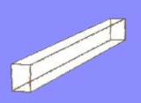
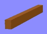
   Projects in RogCAD are built up mostly through the use
of cubic primitives. The user defines a cubic shape by
specifying two diagonally opposite vertices.
RogCAD automatically supplies the remaining six vertices
as well as the connecting lines and planes.
These cubic elements can be skewed, resized, rotated,
translated (slid) and replicated.
Here are some cubics defined in a text file using Notepad:
start x y z x y z
point minimum values maximum values rotation color
----- -------------- -------------- -------- -----
type 1 window frames
001 0 0 0 .5 44 1.5 180 3
011 0 0 48.5 .5 44 51 180 3
021 0 0 1.5 .5 2 48.5 180 3
031 0 42 1.5 .5 44 48.5 180 3
type 2 window frames
041 0 0 0 .5 40 1.5 180 3
051 0 0 48.5 .5 40 51 180 3
061 0 0 1.5 .5 2 48.5 180 3
071 0 38 1.5 .5 40 48.5 180 3
.
.
etc
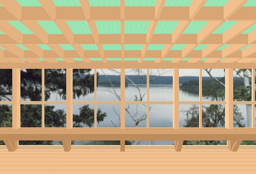
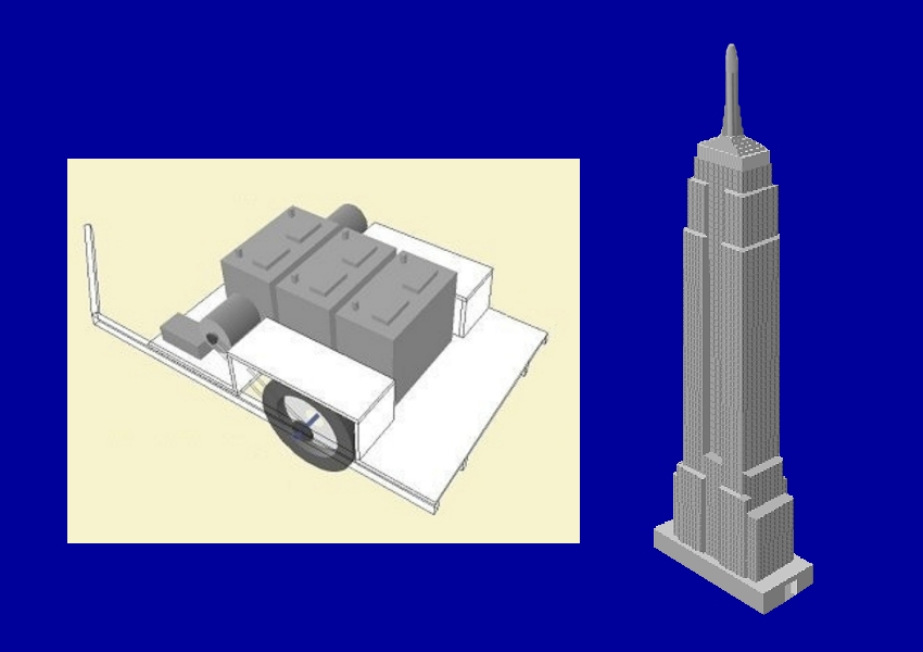
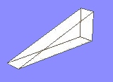
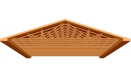
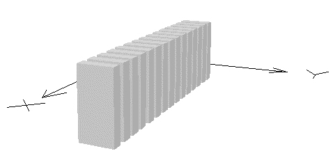
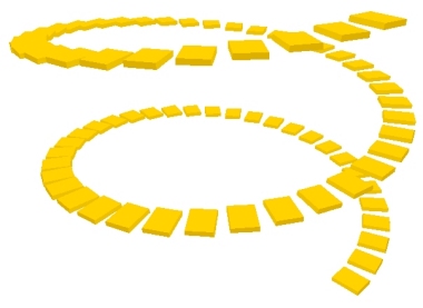
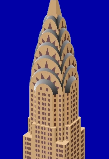
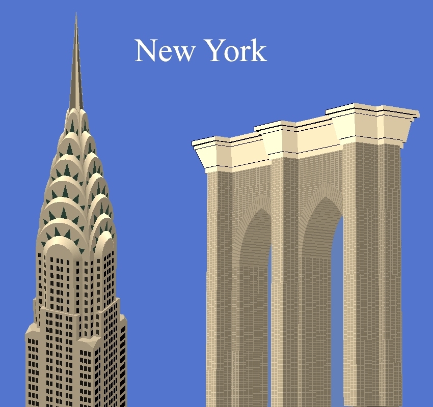
Cubics can also be repeated along straight or curved paths,
then rotated and translated (slid) into position.
Thus generated are things like rows of mitered boards,
windows, rows of buildings and spiral staircases:
Projects in RogCAD are built up mostly through the use
of cubic primitives. The user defines a cubic shape by
specifying two diagonally opposite vertices.
RogCAD automatically supplies the remaining six vertices
as well as the connecting lines and planes.
These cubic elements can be skewed, resized, rotated,
translated (slid) and replicated.
Here are some cubics defined in a text file using Notepad:
start x y z x y z
point minimum values maximum values rotation color
----- -------------- -------------- -------- -----
type 1 window frames
001 0 0 0 .5 44 1.5 180 3
011 0 0 48.5 .5 44 51 180 3
021 0 0 1.5 .5 2 48.5 180 3
031 0 42 1.5 .5 44 48.5 180 3
type 2 window frames
041 0 0 0 .5 40 1.5 180 3
051 0 0 48.5 .5 40 51 180 3
061 0 0 1.5 .5 2 48.5 180 3
071 0 38 1.5 .5 40 48.5 180 3
.
.
etc
Cubics can also be repeated along straight or curved paths,
then rotated and translated (slid) into position.
Thus generated are things like rows of mitered boards,
windows, rows of buildings and spiral staircases:
  x y z x y z spacing endcube rotation color
0 0 0 .292 .292 2.67 5.86 28 270 2
x y z x y z spacing endcube rotation color
0 0 0 .292 .292 2.67 5.86 28 270 2
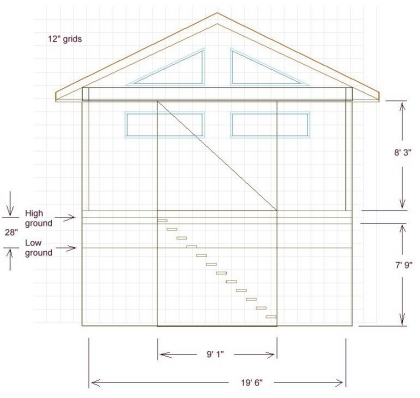
  Points, lines and planes can also be defined independently, and are
integrated with the cubic data structures, as are curved surfaces.
point x y z Connect points:
----- -------------
1 0 63.2 0 LINE GROUP 1:
2 24 63.2 0 8,23 1,12 12,13 2,13
3 24 41.2 0 1,31 8,13 1,2 2,3
4 0 45.2 8 3,18 3,8 5,18 5,6
5 24 0 6 .
6 0 0 6 .
7 0 41.2 6 etc
8 24 41.2 8
9 24 0 8
.
.
etc
Plane data, with light-source shading information:
points
--------------
plane t1 b1 t2 b2 direction color
1 3 8 3 18 270 5
2 18 5 8 9 270 5
3 44 43 2 13 270 5
4 1 2 12 13 180 5
.
.
etc
Rotations and translations are easy:
--------------------------------------------
first last z-angle tran-x tran-y tran-z
ZROTATETRANSLATE:
1 358 115 7 13 0
--------------------------------------------
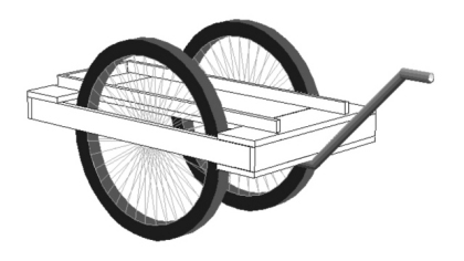
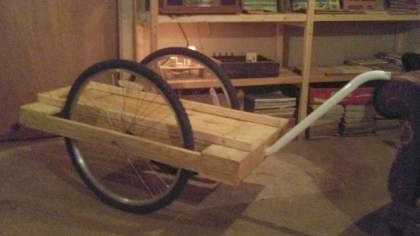
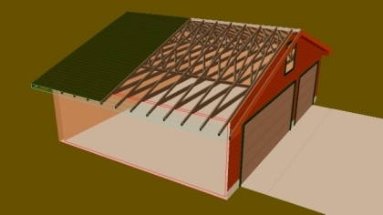
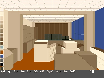
You can build a library of objects, then rotate
and translate (slide) them for precise placement.
Simplest use -- an early image from 1995:
Points, lines and planes can also be defined independently, and are
integrated with the cubic data structures, as are curved surfaces.
point x y z Connect points:
----- -------------
1 0 63.2 0 LINE GROUP 1:
2 24 63.2 0 8,23 1,12 12,13 2,13
3 24 41.2 0 1,31 8,13 1,2 2,3
4 0 45.2 8 3,18 3,8 5,18 5,6
5 24 0 6 .
6 0 0 6 .
7 0 41.2 6 etc
8 24 41.2 8
9 24 0 8
.
.
etc
Plane data, with light-source shading information:
points
--------------
plane t1 b1 t2 b2 direction color
1 3 8 3 18 270 5
2 18 5 8 9 270 5
3 44 43 2 13 270 5
4 1 2 12 13 180 5
.
.
etc
Rotations and translations are easy:
--------------------------------------------
first last z-angle tran-x tran-y tran-z
ZROTATETRANSLATE:
1 358 115 7 13 0
--------------------------------------------
You can build a library of objects, then rotate
and translate (slide) them for precise placement.
Simplest use -- an early image from 1995:
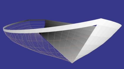
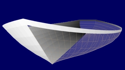
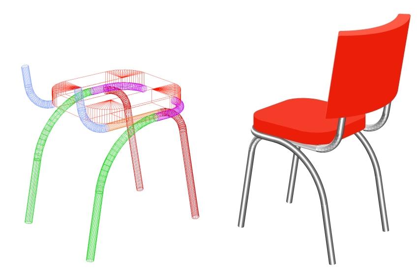
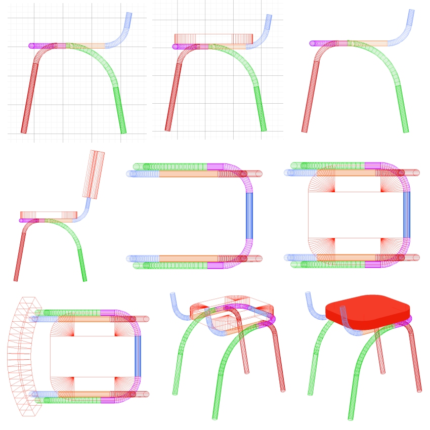
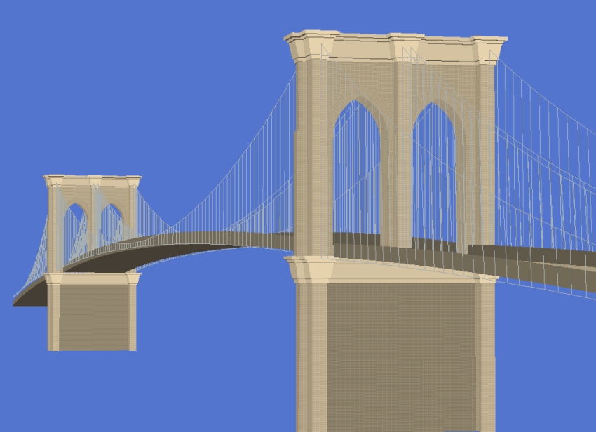
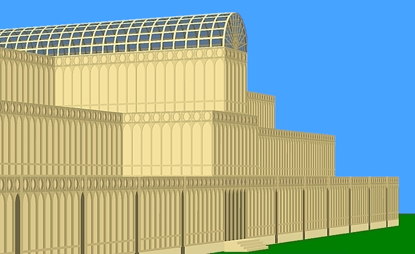
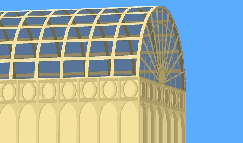
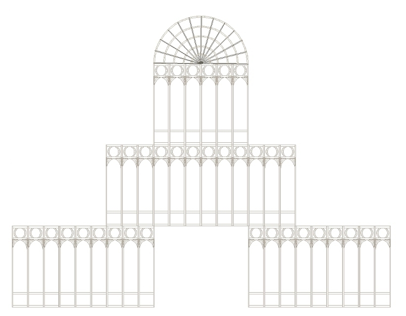
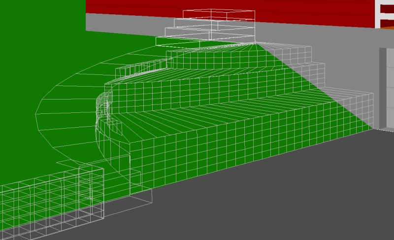
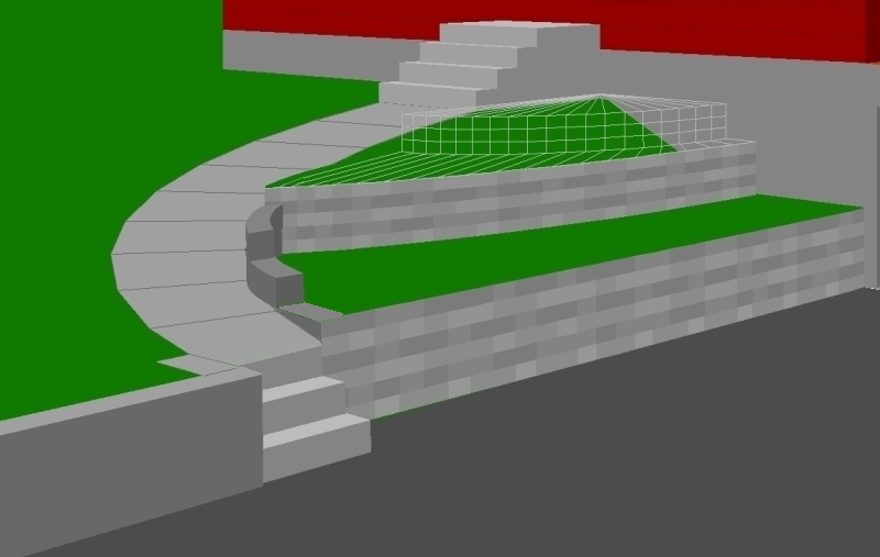
  Complex curved surfaces are modeled by stretching
basic circular shapes in a variety of directions.
Curved elements with unlimited deformation potential:
points degrees radius offset weight
per ----------- ------- ----------- --------
section start arc X Y X Y Z left inc stretch
20
20 -70 19.2 6 24 30 2.83 0 0 0
20 -70 19.2 6 24 30 4.83 0 0 0
20
20 -70 19.2 6 24 30 4.83 0 0 0
3 -87 10 6.9 24 27.6 4.83 0 0 0
20
3 -87 10 6.9 24 27.6 4.83 0 0 0
3 -87 10 6.9 24 27.6 6.17 0 0 0
.
etc
Complex curved surfaces are modeled by stretching
basic circular shapes in a variety of directions.
Curved elements with unlimited deformation potential:
points degrees radius offset weight
per ----------- ------- ----------- --------
section start arc X Y X Y Z left inc stretch
20
20 -70 19.2 6 24 30 2.83 0 0 0
20 -70 19.2 6 24 30 4.83 0 0 0
20
20 -70 19.2 6 24 30 4.83 0 0 0
3 -87 10 6.9 24 27.6 4.83 0 0 0
20
3 -87 10 6.9 24 27.6 4.83 0 0 0
3 -87 10 6.9 24 27.6 6.17 0 0 0
.
etc
The ease with which one can model
       boat hulls in RogCAD is legendary.
|
Set the war aside. This is Russia's "Progress" space cargo ship. Click for dimensions
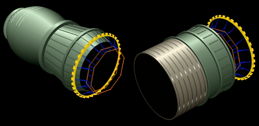
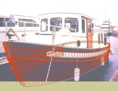
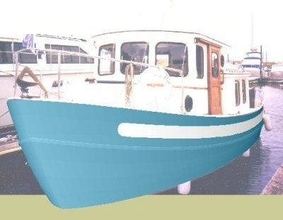 Hull wireframe modeled in RogCAD Hull surface modeled in RogCAD
 Link:
Link: 
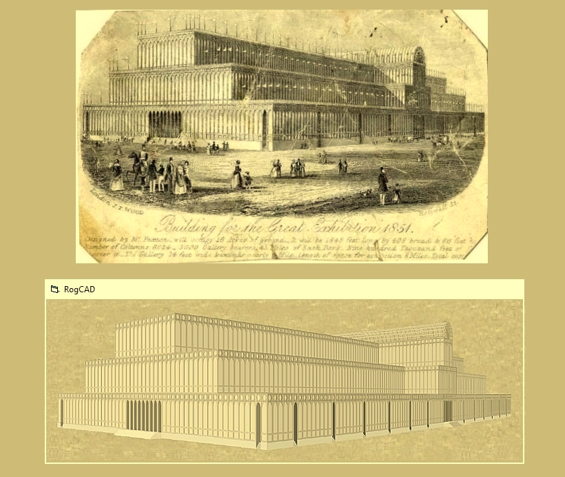
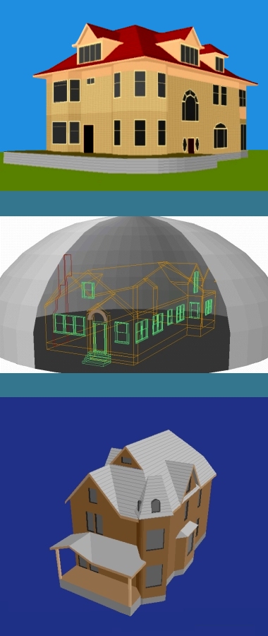
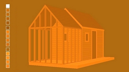
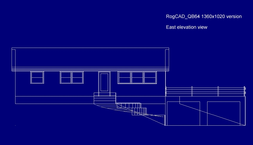
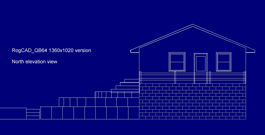
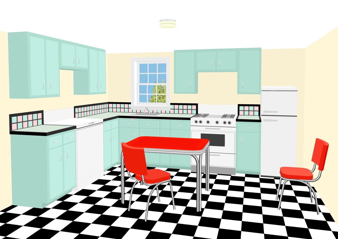
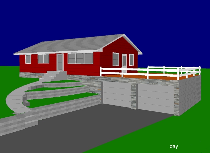
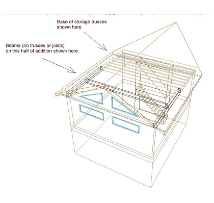
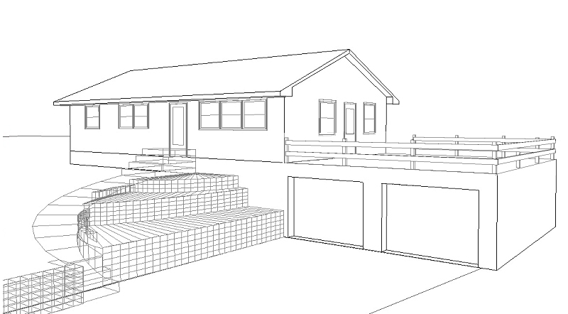
 Facades can be either imported or generated.
Below, is an example of both. The stonework on the
front of the house was imported from a photograph
after using Paint Shop Pro freeware to skew it for
a perspective matching the CAD perspective.
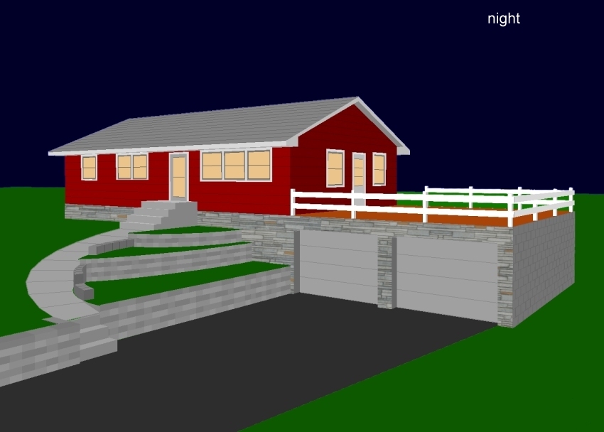
Facades can be either imported or generated.
Below, is an example of both. The stonework on the
front of the house was imported from a photograph
after using Paint Shop Pro freeware to skew it for
a perspective matching the CAD perspective.
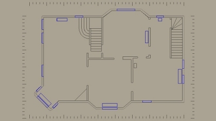
 66 second looping video (two more small videos lower down)
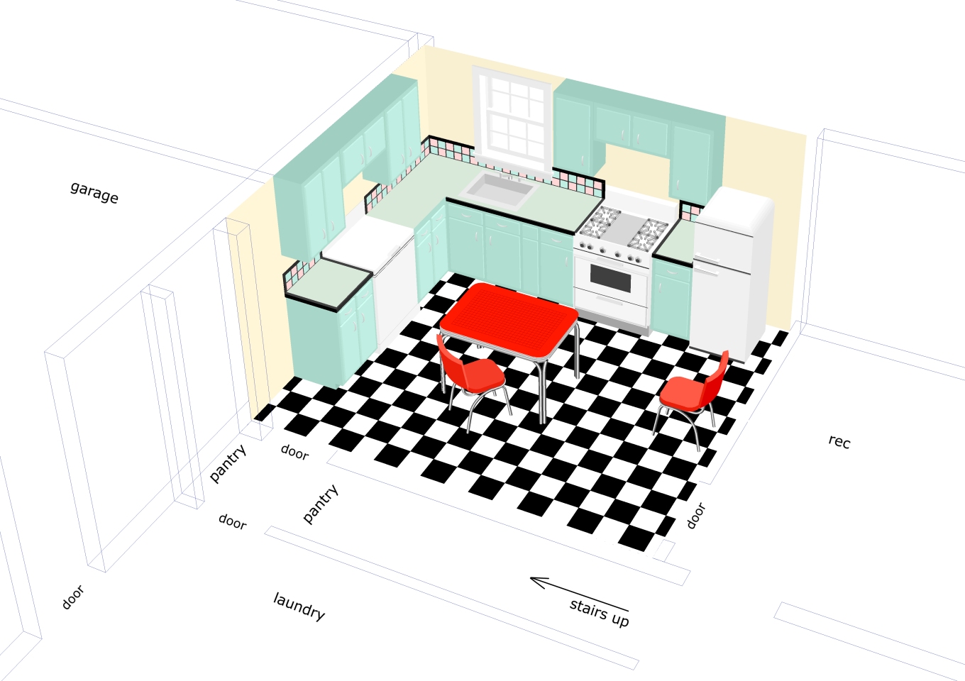
Three options for an addition
66 second looping video (two more small videos lower down)
Three options for an addition
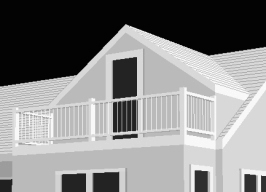
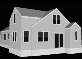
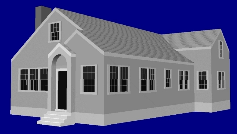
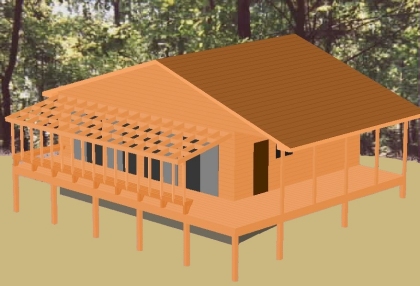
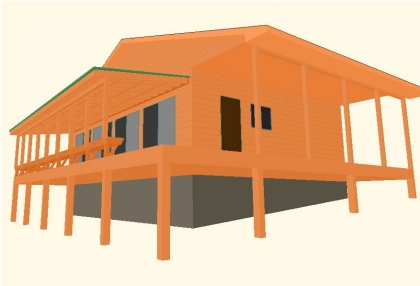
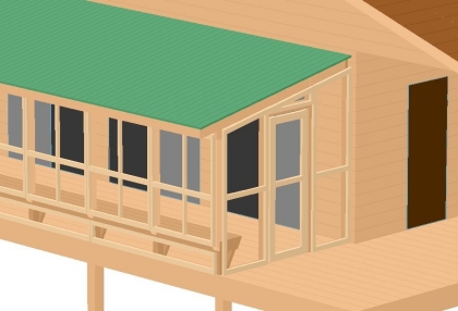
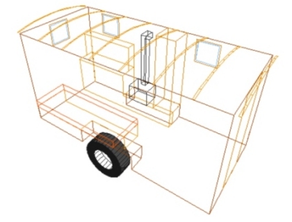
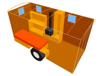
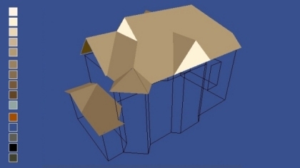
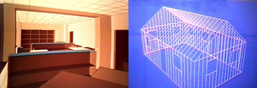
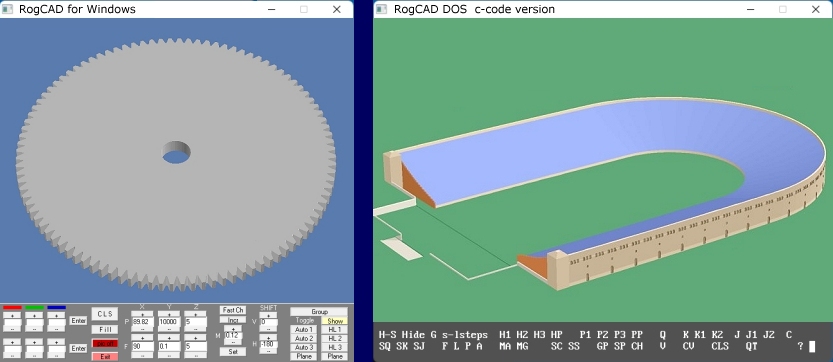
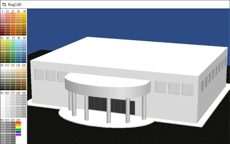
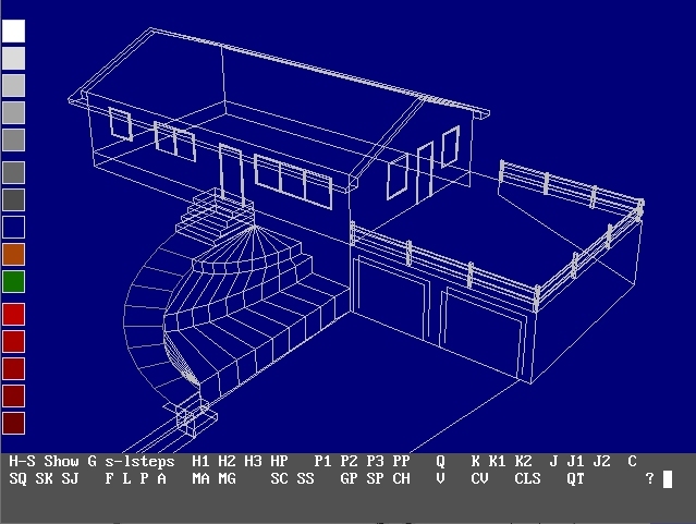 RogCAD for Windows output:
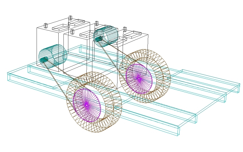
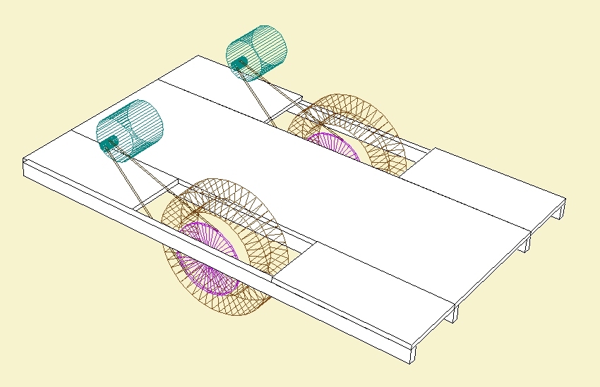
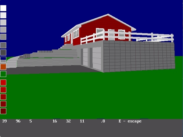
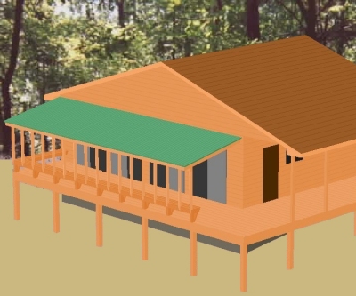
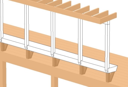
 25 second looping video demonstrating RogCAD's
automatic surface modeling (hidden line removal)
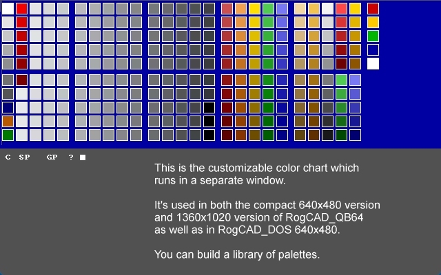
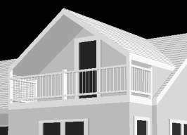
RogCAD for Windows customizable color palette:
25 second looping video demonstrating RogCAD's
automatic surface modeling (hidden line removal)
RogCAD for Windows customizable color palette:
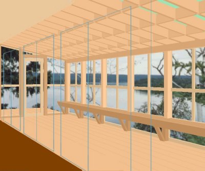
 50 second looping video